An O2 sensor is a galvanic battery that provides the PCM with a voltage signal (0-1 volt) inversely proportional to the amount of oxygen in the exhaust. In other words, if the oxygen content is low, the voltage output is high; if the oxygen content is high the output voltage is low. The PCM uses this information to adjust injector pulse-width to achieve the 14.7–to–1 air/fuel ratio necessary for proper engine operation and to control emissions.
The O2 sensor must have a source of oxygen from outside of the exhaust stream for comparison. Current O2 sensors receive their fresh oxygen (outside air) supply through the O2 sensor case housing.
Four wires (circuits) are used on each O2 sensor: a 12–volt feed circuit for the sensor heating element; a ground circuit for the heater element; a low-noise sensor return circuit to the PCM, and an input circuit from the sensor back to the PCM to detect sensor operation.
Oxygen Sensor Heater Relay: If the vehicle is equipped with 4 oxygen sensors, a separate oxygen sensor relay is used to supply voltage to the sensor heating elements. This particular relay is used only for the 1/2 and 2/2 downstream sensors. Voltage for the other 2 sensor heating elements is supplied directly from the ASD relay. Refer to 8, Wiring Diagrams to determine which relay is used.
To avoid the large simultaneous current surge needed to operate all 4 sensors, power is delayed to the 2 downstream heater elements by the PCM for approximately 2 seconds.
Oxygen Sensor Heater Elements:
The O2 sensor uses a Positive Thermal Co-efficient (PTC) heater element. As temperature increases, resistance increases. At ambient temperatures around 70°F, the resistance of the heating element is approximately 4.5 ohms. As the sensor's temperature increases, resistance in the heater element increases. This allows the heater to maintain the optimum operating temperature of approximately 930°-1100°F (500°-600° C). Although the sensors operate the same, there are physical differences, due to the environment that they operate in, that keep them from being interchangeable.
Maintaining correct sensor temperature at all times allows the system to enter into closed loop operation sooner. Also, it allows the system to remain in closed loop operation during periods of extended idle.
In Closed Loop operation, the PCM monitors certain O2 sensor input(s) along with other inputs, and adjusts the injector pulse width accordingly. During Open Loop operation, the PCM ignores the O2 sensor input. The PCM adjusts injector pulse width based on preprogrammed (fixed) values and inputs from other sensors.
Upstream Sensor - Engine Equipped With 2 Sensors: The upstream sensor (1/1) provides an input voltage to the PCM. The input tells the PCM the oxygen content of the exhaust gas. The PCM uses this information to fine tune fuel delivery to maintain the correct oxygen content at the downstream oxygen sensor. The PCM will change the air/fuel ratio until the upstream sensor inputs a voltage that the PCM has determined will make the downstream sensor output (oxygen content) correct.
The upstream oxygen sensor also provides an input to determine catalytic convertor efficiency.
Downstream Sensor - Engine Equipped With 2 Sensors: The downstream oxygen sensor (1/2) is also used to determine the correct air-fuel ratio. As the oxygen content changes at the downstream sensor, the PCM calculates how much air-fuel ratio change is required. The PCM then looks at the upstream oxygen sensor voltage and changes fuel delivery until the upstream sensor voltage changes enough to correct the downstream sensor voltage (oxygen content).
The downstream oxygen sensor also provides an input to determine catalytic convertor efficiency.
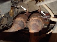
Upstream Sensors - Engine Equipped With 4 Sensors: Two upstream sensors are used (1/1 and 2/1). The 1/1 sensor is the first sensor to receive exhaust gases from the #1 cylinder. They provide an input voltage to the PCM. The input tells the PCM the oxygen content of the exhaust gas. The PCM uses this information to fine tune fuel delivery to maintain the correct oxygen content at the downstream oxygen sensors. The PCM will change the air/fuel ratio until the upstream sensors input a voltage that the PCM has determined will make the downstream sensors output (oxygen content) correct.
The upstream oxygen sensors also provide an input to determine mini-catalyst efficiency. Main catalytic convertor efficiency is not calculated with this package.
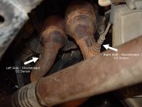
Downstream Sensors - Engine Equipped With 4 Sensors: Two downstream sensors are used (1/2 and 2/2). The downstream sensors are used to determine the correct air-fuel ratio. As the oxygen content changes at the downstream sensor, the PCM calculates how much air-fuel ratio change is required. The PCM then looks at the upstream oxygen sensor voltage, and changes fuel delivery until the upstream sensor voltage changes enough to correct the downstream sensor voltage (oxygen content).
The downstream oxygen sensors also provide an input to determine mini-catalyst efficiency. Main catalytic convertor efficiency is not calculated with this package.
Engines equipped with either a downstream sensor(s), or a post-catalytic sensor, will monitor catalytic convertor efficiency. If efficiency is below emission standards, the Malfunction Indicator Lamp (MIL) will be illuminated and a Diagnostic Trouble Code (DTC) will be set..