...and I got relays on my mind, yes I got relays on my mind

Got the whole shooting match finally wired up, just a little plumbing and it'll be ready for a full test. Just in case those 40amp relays don't cut the mustard with the Contour/Mystique fan setup (I have them wired independantly) I preassembled two 70 amp relay pigtails using the Hella connectors and sockets and a sample of the applicable color coded Ford wire. Soldered the works together and it turned out very well. [TABLE="class: ncode_imageresizer_warning"]
[TR]
[TD="class: td1, width: 20"]
wol_error-1.gif
[/TD]
[TD="class: td2"]This image has been resized. Click this bar to view the full image.[/TD]
[/TR]
[/TABLE]
8749426424_6952d76175_c-1.jpg
 
I hope that I installed the diode the right way;

8783388303_5ea2783816_c-1.jpg


8789977718_014402f8a8_c-1.jpg


Edit: Got the switch wired in and as it turns out didn't need to be grounded to function, it was the inclusion of that diode.
 
Last edited:

pen_lamp_materials_diode-1.jpg

pen_solar_diode_detail-1.jpg

Current will flow from the no band side to the band side (in the direction of the arrow in the schematic representation)


Hope this helps
 
Thanks JPN, I'm a novice when it comes to electornics, but understand that current flows like water through a hose and that diode is kinda like a one way gate valve.:coffee:
Apparently since the switch controls a relay and that relay is grounded that completes the operating circuit?
 
Last edited:
I'm now proceeding to solder in wiring for other electrics (driving lights, fog lights, headlights, etc) into that relay/fuse box. Luck thing I did as a primary wire to the starter solenoid was coming loose from its connector. Searched the garage and found my old hobby vise I've had since the late 60's and crushed the collar around the wire, going to attempt to resolder tonight using my lil butane torch.
 

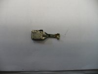
Well since I wanted to adapt some of the other relays for higher amps (40 amp, not like the graft I did for the 70 amp relay though). Upgrading from 16 to 12 gauge wire but since these connectors

9035363371_fcf8495e66_b.jpg

were going back into the Ford PDB, I had very limited space to get them into their nacelles.

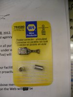
Luckily NAPA had available what they call Parallel Connectors

9037586682_5c8769c332_b.jpg

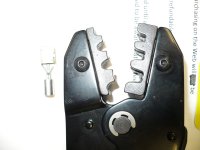
..that slipped over the ends of the connectors nicely and using my trusty racheting crimpers

9035361657_12902a7534_b.jpg

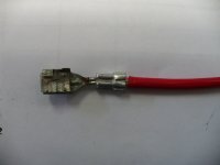
...I was able to get a nice clean crimp, ready for solder and fit into the PBD nacells with a perfect 'click' of the holdfast

9037588396_db594c86bc_b.jpg

Next step is to test all of the circuits and switches and then a road test.
 
Well nutz, the override switch was working (for test) until yesterday. Flipping the override switch and I hear the relay click but the fans don't spin, maybe it was a mistake to solder the wires directly to the switch. There's power to the switch, so going to trace from there tonight, unless I have a scheisse day like yesterday.
 
Well nutz, the override switch was working (for test) until yesterday. Flipping the override switch and I hear the relay click but the fans don't spin, maybe it was a mistake to solder the wires directly to the switch. There's power to the switch, so going to trace from there tonight, unless I have a scheisse day like yesterday.

I am no technition but once tried to solder where crimp connectors usually go too and even using a heat sink did not help dissipate heat very well . I think I overheated the connectors with a pin point butane too . The torch is fine for heavier gauge soldering such as 12 gauge but from what I had happen , torch heat is not very kind to sensitive electronics and devices. Hope that the do over will be successful , I guess I'm thankful for you that it is only a switch , not a component !
 

Well, I felt those donkey ears spring up last night! :scratch: Was tracing wires with my Ohm/Volt meters and going from power to the switch to the first bank of relays and checking each one for power in/out I found one that failed. Suspecting a blown relay due to jumping connectors with a test wire I inspected the wiring to that specific 'Override' circuit relay and I found the ground wire had been pulled from the ground bus I installed on the firewall. ~ DOI! :crazy:
 
BTW I see the wiring to the headlights is one black and two grey, one with a tracer anyone know what color is that tracer is, white or black?
Thanks and a lift of the lynch lid.

Got the grey 12 gauge wire in today going to brave the garage heat and see if I can find out.
 
Last edited:
....the tracer is white. Found Sharpie makes a wax like white marker that I used to draw a tracer on one of the paired gray wires. Great stuff this, after it sets it is flexible enough to be bent 180* inside of an inch with no chipping or fading lke paint pens.

Juuuust about got the wiring done, just have to connect my grounds (glad I ran a bunch of spares withing easy reach from the grounding bus bar).
 

Well, all seems well. Initially the high speed controller was setting the fans on too early so I'm in the process of modulating at what point the low speed and the high speed engage. Go figure one week before completion we finally had a hot spell (for western Oregon) that would've been prime time to set this up. Now we're in the '60's :roll:
 

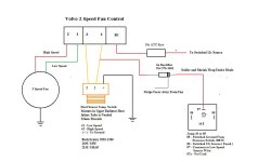
Yes it is. This is the diagram I made up for the use of the A/C system. It's been in there for a year now with zero issues. Maybe you can use this to help with your installation.
 
Thanks Catoctin, but this is the completion (for now anyways) of the year long upgrade that began with my botched relocation of a fan being used as a pusher when I first got BB to an underhood electrical upgrade encompassing this Ford Relay-Fuse power distribution box, and the related circuitry to; each of the twin Merc Mystique (Ford Coutour) fans (fused, relayed and controlled independantly) the headlights (for higher amp Flösser branded H4's), the fog and driving/spotlights (higher amp H3's). Also I wired in an absolute ground bus bar to ground everything I could find to the negative battery post of my primary battery. As I work 7 days a week this took some time for research, development and implementation. My most hearty thanks to the friendly folks that helped me along here and elsewhere in other forums.
 
Back
Top