Angry sparrows
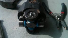
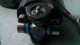
You’ll see many people on Jeep forums talk about hearing what sounds like angry sparrows coming from the front of their Jeep. The normal cause for this is the ball centering unit of your front driveshaft. In my case, I was hearing a squeak coming from my front driveshaft – I only heard it in 4WD, and it increase in frequency the faster I went. It turned out to be a bad u-joint.
What if I just ignore it?
If you ignore worn out driveshaft components then they’ll fail. The problem with a failed u-joint is that the driveshaft will essentially come free at one end – this results in a twenty pound metal bar spinning wildly at high RPMs and destroying things around it (namely your transfer case). You’re going to have a bad day.
Jeep Driveshafts
A run of the mill Jeep will have two driveshafts – a traditional driveshaft in the rear, with a ujoint on each end, and what’s called a dual cardan driveshaft in the front. A dual cardan driveshaft has one ujoint on the axle end of the driveshaft, and what amounts to two ujoints at the transfer case side.
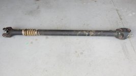
This is the front driveshaft from my 2005 Wrangler TJ
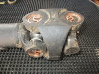
And this is an up close view of the double cardan
Removing the front driveshaft:
To start, you’ll have to make a decision – remove the driveshaft with your skidplate on, or take the skidplate off. If you decide to remove the skidplate, remember that it supports most of your drivetrain – you’ll need to support it with a jack stand or the like, or everything will drop when you pull the skid off. I decided to remove the driveshaft with the skidplate on.
Start by removing the 8 bolts that hold the driveshaft to the transfer case. This is a view from the side, and you can see two of the four bolts to be removed.
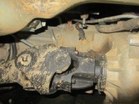
As you can see from this picture there isn’t much room to work. I found it easiest to remove the two bolts that I could reach, then pull the Jeep forward 12 inches, which would rotate the driveshaft, and the two remaining bolts would become accessible.
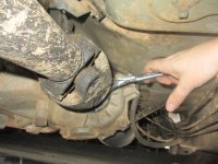
Once all four bolts were out, I removed the axle side (it’s held on by 4 bolds in a similar fashion). Be careful at this point not to let the driveshaft fall on your head. It’s heavy, and the ER can eat up all your Jeep money.
I noticed right away that these u-joints were long overdue for replacement.
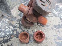
Rebuilding the driveshaft
Replacement parts:
(1) Spicer 211544X Socket yoke assembly
(3) Spicer 5-1310X Ujoints
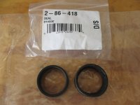
(1) Spicer 2-86-418 rubber boot
Stock Jeep u-joints and ball centering units are not greaseable, as in they don’t have grease fittings. I decided to replace my equipment with similar non-greaseable parts. There are u-joints and ball centering units out there that have grease fittings – just keep in mind that it uses a special needle adapter for your grease gun.
The ball centering unit is rebuildable. I originally intended to do this, and ordered what turned out to be the wrong rebuild kit. After a bit of frustration, I decided to just order a replacement ball centering unit.
To start, you’ll need to remove the existing parts.
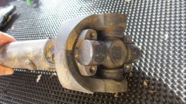
Here are some photos of the CV / double cardan portion of the driveshaft
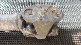
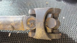
At the end, you can see the ball centering unit’s ears, behind the outer u-joint
Just use a pair of snap ring pliers if you have them – if not needle-nose pliers should work, and remove the snap rings from your u-joints.
Just compress the snapring
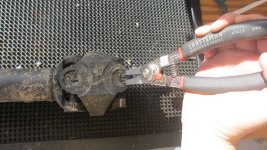
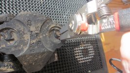
If it doesn’t pop out, you can use a flat screwdriver to help it out. Careful, it will fly out (and halfway across the room).
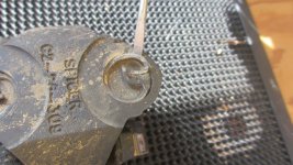
Once you have the snap-rings removed from each side of the u-joint, it’s time to pull the joint out. There are several ways to do this – most people will use a u-joint press. I decided to try a big hammer instead.
I found a large socket that was larger than the u-joint cup, so that when I pounded it down, the u-joint cup would go into the socket.
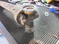
I then put a socket on top of the u-joint that was slightly smaller than the cup
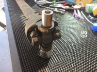
And give it some good whacks
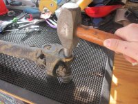
You can see here that I’ve pushed the u-joint as far down as it will go. You just take some pliers and pull off the exposed cup. After that, you flip the joint over, and use your smaller socket to pound the joint down, and remove the second cup.
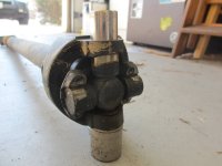
Here you can see the ball centering unit (after the outer u-joint is removed). At this point it just falls off – the u-joint was the only thing holding it on. Keep in mind there is a spring that is easy to lose if you’re not careful.
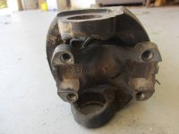
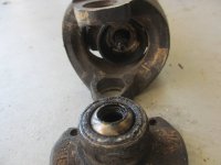
Now it’s time to remove the inner u-joint. I set things up the same way – large socket on the bottom, smaller one on top. I then whack it until the joint bottoms out.
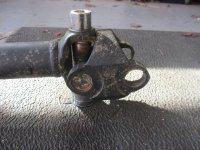
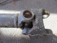
I then flipped the driveshaft over, and used my pliers to pull the cap off. I pounded down the other side, removed its cap too. Finally, I repeated this procedure on the connecting piece.
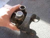
Reassembly
You’ll want to very carefully pull two caps off of your new joint, and insert it into the driveshaft. Be sure not to let the pins fall out of the cap (it’s fairly well greased, so as long as you don’t drop it, you should be fine). Also, try not to get the exposed u-joint arms dirty, as grit inside your u-joints is not a good thing.
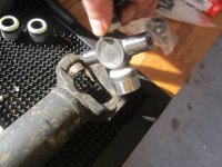
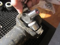
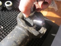
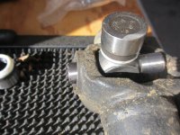
Once in place, carefully slide the cap onto your u-joint from the outside. Keep in mind that you want the pins lined up around the inside of you cap, and you don’t want to knock them down.
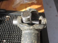
Now, put the cap on the opposite end, and gently tap it into place with your hammer. Here you can see the u-joint in place
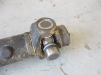
I then tapped down the cap some (probably more than I needed), and put the snap ring on
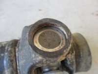
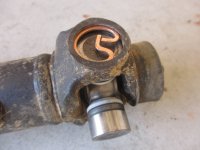
Flip the driveshaft over, and do the same thing
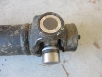
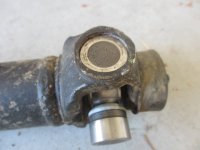
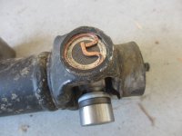
Now, do the same thing with our connector
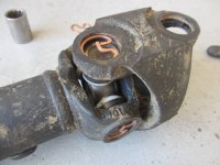
I went ahead and replaced the rubber boot on my driveshaft – this is optional, and actually turned out to be one of the most frustrating parts of the whole install. The rubber boot has a metal collar at the bottom – you should be able to simply slide the boot on, but in my case it just wouldn’t go. I ended up destroying one boot by trying to use a screwdriver to tap it into place. My advice is to take your time.
The new boot is on the left, and the original is on the right
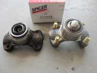
And the boot / seal installed
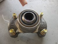
Next comes the ball centering unit / socket yoke assembly. I went ahead and replaced mine. Here you can see the old and new ones (the new one came with new bolts.
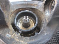
Just pull out the white plastic plug – it’s there to keep grease in, and debris out.
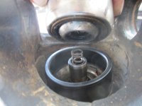
With the spring sitting in its spot on the driveshaft, put the yoke assembly in position.
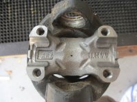
It isn’t actually bolted to anything – the final (outer) u-joint will hold it into place
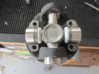
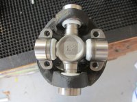
Now, put the u-joint clips in place for the outer u-joint
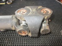
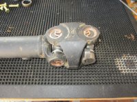
At this point the rebuild is done, and you just need to re-install. I started with the axle end, then moved onto the transfer case end.
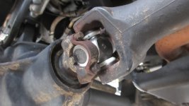

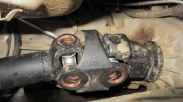
Overall this isn’t a bad job – it took me a couple of days, mainly because I’m lazy, and an hour’s worth of work and I'm ready to go back inside... If you have all the tools and parts, this is probably a 2-3 hour job.
You’ll see many people on Jeep forums talk about hearing what sounds like angry sparrows coming from the front of their Jeep. The normal cause for this is the ball centering unit of your front driveshaft. In my case, I was hearing a squeak coming from my front driveshaft – I only heard it in 4WD, and it increase in frequency the faster I went. It turned out to be a bad u-joint.
What if I just ignore it?
If you ignore worn out driveshaft components then they’ll fail. The problem with a failed u-joint is that the driveshaft will essentially come free at one end – this results in a twenty pound metal bar spinning wildly at high RPMs and destroying things around it (namely your transfer case). You’re going to have a bad day.
Jeep Driveshafts
A run of the mill Jeep will have two driveshafts – a traditional driveshaft in the rear, with a ujoint on each end, and what’s called a dual cardan driveshaft in the front. A dual cardan driveshaft has one ujoint on the axle end of the driveshaft, and what amounts to two ujoints at the transfer case side.
This is the front driveshaft from my 2005 Wrangler TJ

And this is an up close view of the double cardan

Removing the front driveshaft:
To start, you’ll have to make a decision – remove the driveshaft with your skidplate on, or take the skidplate off. If you decide to remove the skidplate, remember that it supports most of your drivetrain – you’ll need to support it with a jack stand or the like, or everything will drop when you pull the skid off. I decided to remove the driveshaft with the skidplate on.
Start by removing the 8 bolts that hold the driveshaft to the transfer case. This is a view from the side, and you can see two of the four bolts to be removed.

As you can see from this picture there isn’t much room to work. I found it easiest to remove the two bolts that I could reach, then pull the Jeep forward 12 inches, which would rotate the driveshaft, and the two remaining bolts would become accessible.

Once all four bolts were out, I removed the axle side (it’s held on by 4 bolds in a similar fashion). Be careful at this point not to let the driveshaft fall on your head. It’s heavy, and the ER can eat up all your Jeep money.
I noticed right away that these u-joints were long overdue for replacement.

Rebuilding the driveshaft
Replacement parts:
(1) Spicer 211544X Socket yoke assembly
(3) Spicer 5-1310X Ujoints
(1) Spicer 2-86-418 rubber boot
Stock Jeep u-joints and ball centering units are not greaseable, as in they don’t have grease fittings. I decided to replace my equipment with similar non-greaseable parts. There are u-joints and ball centering units out there that have grease fittings – just keep in mind that it uses a special needle adapter for your grease gun.
The ball centering unit is rebuildable. I originally intended to do this, and ordered what turned out to be the wrong rebuild kit. After a bit of frustration, I decided to just order a replacement ball centering unit.
To start, you’ll need to remove the existing parts.
Here are some photos of the CV / double cardan portion of the driveshaft


At the end, you can see the ball centering unit’s ears, behind the outer u-joint

Just use a pair of snap ring pliers if you have them – if not needle-nose pliers should work, and remove the snap rings from your u-joints.
Just compress the snapring


If it doesn’t pop out, you can use a flat screwdriver to help it out. Careful, it will fly out (and halfway across the room).

Once you have the snap-rings removed from each side of the u-joint, it’s time to pull the joint out. There are several ways to do this – most people will use a u-joint press. I decided to try a big hammer instead.
I found a large socket that was larger than the u-joint cup, so that when I pounded it down, the u-joint cup would go into the socket.

I then put a socket on top of the u-joint that was slightly smaller than the cup

And give it some good whacks

You can see here that I’ve pushed the u-joint as far down as it will go. You just take some pliers and pull off the exposed cup. After that, you flip the joint over, and use your smaller socket to pound the joint down, and remove the second cup.

Here you can see the ball centering unit (after the outer u-joint is removed). At this point it just falls off – the u-joint was the only thing holding it on. Keep in mind there is a spring that is easy to lose if you’re not careful.


Now it’s time to remove the inner u-joint. I set things up the same way – large socket on the bottom, smaller one on top. I then whack it until the joint bottoms out.


I then flipped the driveshaft over, and used my pliers to pull the cap off. I pounded down the other side, removed its cap too. Finally, I repeated this procedure on the connecting piece.

Reassembly
You’ll want to very carefully pull two caps off of your new joint, and insert it into the driveshaft. Be sure not to let the pins fall out of the cap (it’s fairly well greased, so as long as you don’t drop it, you should be fine). Also, try not to get the exposed u-joint arms dirty, as grit inside your u-joints is not a good thing.


Once in place, carefully slide the cap onto your u-joint from the outside. Keep in mind that you want the pins lined up around the inside of you cap, and you don’t want to knock them down.

Now, put the cap on the opposite end, and gently tap it into place with your hammer. Here you can see the u-joint in place

I then tapped down the cap some (probably more than I needed), and put the snap ring on


Flip the driveshaft over, and do the same thing


Now, do the same thing with our connector

I went ahead and replaced the rubber boot on my driveshaft – this is optional, and actually turned out to be one of the most frustrating parts of the whole install. The rubber boot has a metal collar at the bottom – you should be able to simply slide the boot on, but in my case it just wouldn’t go. I ended up destroying one boot by trying to use a screwdriver to tap it into place. My advice is to take your time.
The new boot is on the left, and the original is on the right

And the boot / seal installed

Next comes the ball centering unit / socket yoke assembly. I went ahead and replaced mine. Here you can see the old and new ones (the new one came with new bolts.

Just pull out the white plastic plug – it’s there to keep grease in, and debris out.

With the spring sitting in its spot on the driveshaft, put the yoke assembly in position.


It isn’t actually bolted to anything – the final (outer) u-joint will hold it into place


Now, put the u-joint clips in place for the outer u-joint


At this point the rebuild is done, and you just need to re-install. I started with the axle end, then moved onto the transfer case end.


Overall this isn’t a bad job – it took me a couple of days, mainly because I’m lazy, and an hour’s worth of work and I'm ready to go back inside... If you have all the tools and parts, this is probably a 2-3 hour job.
Last edited:

